Lab 2 – Line-follower with State Machine
Objectives
The goal of this lab is to learn more about controllers in Webots via the implementation of state machine to make the robot follow a line. You will also run code to investigate sensor values and test motors.
Pre-requisites
- You must have Webots R2022a (or newer) properly configured to work with Python.
- You must know how to create a robot controller in Python and how to run a simulation in Webots.
- You must have a basic understanding of robot behaviors and how to implement them in Python, as described in the Jupyter Notebook Implementation of simple robot behaviors.
- You must know about Finite-State Machines and how to implement them in Python, as described in the Jupyter Notebook Selecting Behaviors with Finite-State Machines.
If necessary, please go back to Lab 1 and complete the corresponding tasks.
The e-puck robot
Webots contains a realistic model of e-puck, a small differential-drive mobile robot. The movement of this type of robot is controlled by independently adjusting the speeds of the left and right wheels.
The e-puck robot has multiple sensors. To detect obstacles, the e-puck contains 8 infrared distance sensors around its body. Optionally, 3 infrared sensors can be mounted under its base, pointing to the floor, allowing the implementation of a line-following behavior.
An explanation about the e-puck robot and how to use it in Webots is available here.
Tasks
1- Follow Webots Tutorial 4 to better understand the e-puck model and learn how to control it in Python. Note: Webots Tutorials 2 and 3 are optional: you can complete these Robotics Simulation Labs without them. However, you are encouraged to follow all Webots tutorials if you want to better understand how the simulation is implemented.
2- After finishing tutorial 4, open the line-following sample world: Click on File > Open Sample Worlds and go to robots > gctronic > e-puck and select e-puck_botstudio_with_floor_sensors.wbt. You should see a world similar to the one shown in Figure 1. In the next steps you must use the e-puck robot that is loaded with this sample world because it has the floor sensors to detect the line.
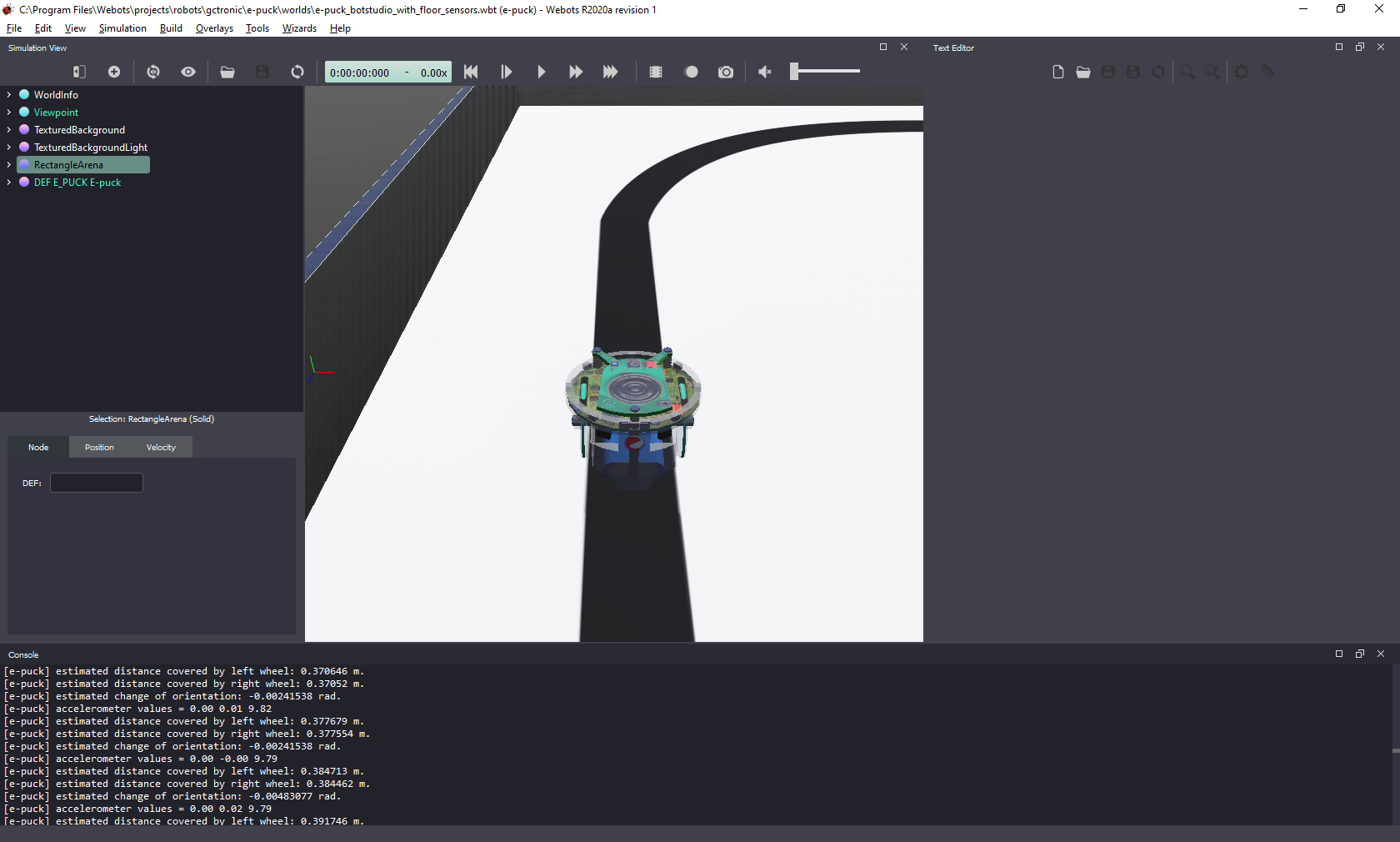
Figure 1. Webots screenshot with the world “e-puck_botstudio_with_floor_sensors.wbt”.
3- You will need to make changes to the file, but Webots will not allow you to save changes to the sample world. To be able to do it, first save the sample world with a different name on a folder of your choice.
4- Create a new robot controller in Python and call it “test_sensors”.
5- Copy the code from this script into your test_sensors.py controller. Run it to investigate the values returned by the ground sensors when the robot is over the white floor and over the black line. While running the simulation, you can click the robot and move it to different positions of the field using the arrows. More information about how to read the ground sensors is given below.
6- Adjust the script to investigate the values returned by the proximity sensors and encoders under different conditions. To test the proximity sensors, you can move the robot manually. But to test the encoders, you must change the motor speeds.
7- Change the motor speeds to investigate how fast the robot can run and turn in order to follow the line.
8- Now, use the test_sensors code as a template and create a new controller to implement the line-following behavior based on the finite-state machine shown in Figure 2.
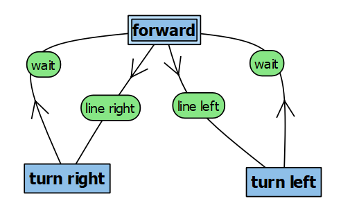
Figure 2. A state machine diagram that implements a simple line-follower behavior.
9- Finally, add one extra state to make the robot run backwards when no line is detected.
Ground sensors
In Tutorial 4 you made use of the distance sensors around the robot. To detect the line on the floor you need to use the ground sensors, instead. The simulator also treats the ground sensors as distance sensors because they are of the same type (infrared sensors). In Python you can access the ground sensors as shown below.
To initialize the ground sensors:
gs = []
gsNames = ['gs0', 'gs1', 'gs2']
for i in range(3):
    gs.append(robot.getDevice(gsNames[i]))
    gs[i].enable(timestep)
To read the ground sensors inside the main loop:
gsValues = []
for i in range(3):
    gsValues.append(gs[i].getValue())
To read sensor values inside the main loop:
line_right = gsValues[0]
line_center = gsValues[1]
line_left = gsValues[2]
Solution
Try to implement the state machine yourself before checking the solution! A possible solution (without the extra state) is available here.
The video below shows the solution code in action:
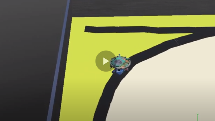 .
.
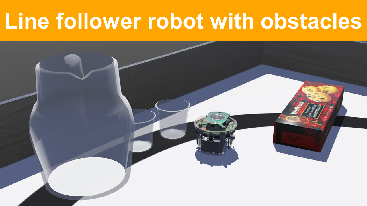
Challenge: Obstacle Avoidance
Change the state machine to make e-puck avoid obstacles placed on its way. You can choose the type of obstacle to add: different formats might require different strategies of obstacle avoidance. Obstacles with round or rectangular shape usually are the less demanding, while obstacles with U-shape require more complex strategies.
An illustration of obstacle avoidance with state machine is given in Figure 3. Note that the obstacle avoidance strategy that was implemented required four extra states, some executing the same action as others. The animation in Figure 3 shows the active state (in red) for each condition during the simulation.
Figure 3. Illustration of obstacle avoidance strategy added to the existing line-follower state machine.
Student Wilfred van Reenen made the video below to illustrate the excellent performance of his obstacle avoidance state machine. If you want to go above and beyond, try to get your robot to avoid all those obstacles!
 .
.
Conclusion
After following this lab you should know more about the e-puck robot model and its sensors, how to program a controller for it in Python, and how to program a robot behavior based on state machine.
Next Lab
In the next lab we will implement another line-following behavior, but using the robot camera as a sensor. For that, you will learn how to process the images to extract relevant information to control the robot.
Go to Lab 3 - Vision-based Line-following Behavior
Back to main page.