Lab 7 - Combine Behaviors to Complete a Mission
Objectives
The main goal of this lab is to combine what you learned in previous labs to program your robot perform a complex mission. You will use robot sensors (including its camera) and a state machine to select behaviors for the robot to navigate a maze while tracking its pose.
Pre-requisites
- You must have Webots R2023a (or newer) properly configured to work with Python (see Lab 1).
- You must know how to create a robot controller in Python and how to run a simulation (see Lab 1).
- You must know how to implement simple behaviors, a state machine, a localization algorithm and a controller for robot navigation (either PID or trajectory tracking).
Tasks and Robot Mission
Download the file webots-maze.zip and unzip it in a folder of your preference. After unzipping the file, open the world ...\webots-maze\worlds\e-puck_maze.wbt. You should see an environment similar to the one shown in Figure 1.
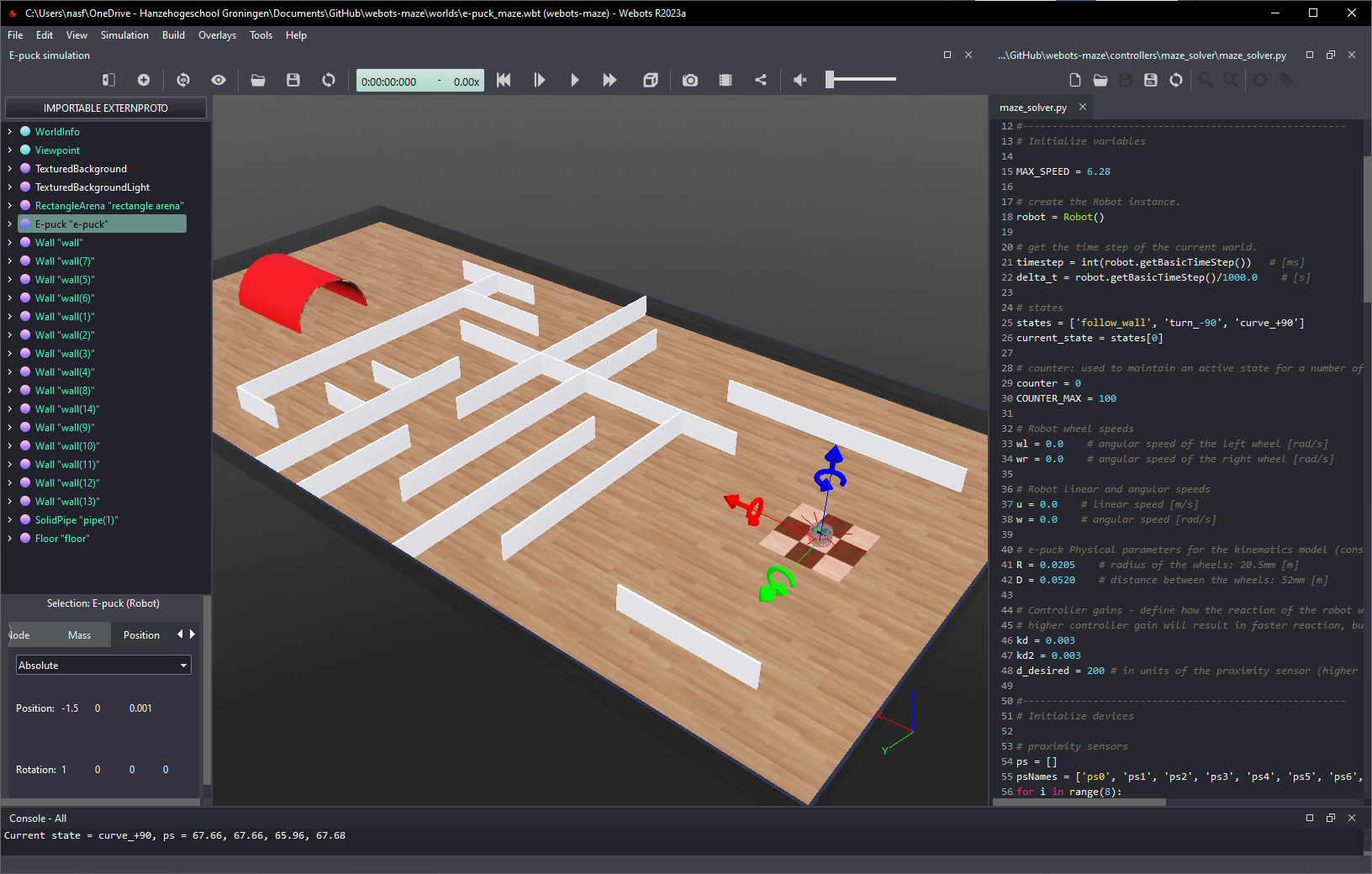
Figure 1. Screenshot showing the maze environment. The e-puck robot starts at the center of the checker texture square (right) and must navigate to the red tunnel (left).
The mission of your robot is to pass under the red tunnel. The e-puck robot starts at the center of the checker texture square (right) and must navigate through the maze to get to the red tunnel (left). The robot can follow any free path (it does not need to be the shortest nor the fastest).
Requirements
There are many ways to implement a program for the robot to complete this mission. But for this assignment you must implement concepts from other labs. The list of requirements is given below:
- Odometry-based localization algorithm must be implemented to keep track of the robot pose. As it navigates, its position and orientation must be printed to the console.
- Go-to-goal controller with PID or trajectory tracking controller must be implemented to move the robot when not inside the corridors of the maze (or when far from the walls). The controller must generate reference values for linear and angular velocities.
- Wall-following or corridor-following must be implemented to move the robot when inside the corridors of the maze. The behavior must generate reference values for linear and angular velocities.
- A state machine must be implemented to select the behaviors and controllers to complete the mission. The active state must be printed to the console.
- The robot must be able to complete its mission even if the maze is changed.
For the demonstration, you must first show that the robot completes its mission with the original environment (as provided in the ZIP file). Then, the maze will be changed and your robot must also complete the mission successfully.
Although not required, you are allowed to use images from the robot’s camera to localize the red tunel and/or to navigate the maze - you can use the camera intead of, or in combination with, the proximity sensors.
Figure 2 illustrates the e-puck robot navigating through the maze by switching between three different behaviors: wall-following, curve +90 deg and turn -90 deg.
Figure 2. Maze navigation by switching between three simple behaviors: wall-following, curve +90 degrees and turn -90 degrees.
The selection of the active behavior is done by the state machine diagram shown in Figure 3, which uses the proximity sensor readings for transitions between states. For completing the mission described above, other states must be added to first make the robot move towards the maze, and to make the robot move to the red tunnel once it gets to the other side of the maze. The number of states you are going to add and their associated behaviors is up to you.
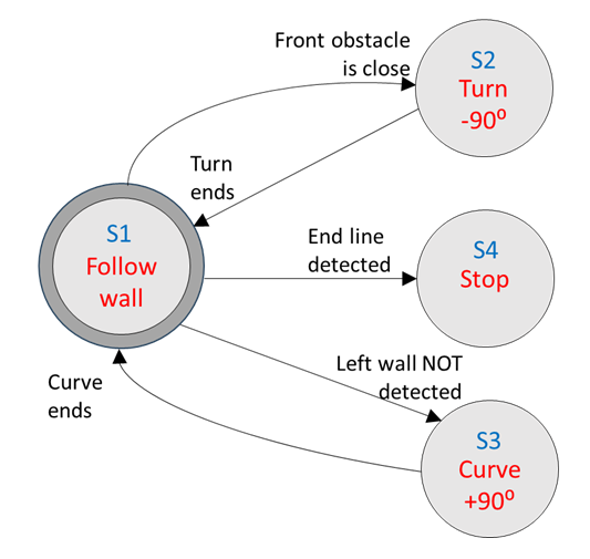
Figure 3. Maze-solver state machine diagram.
As mentioned, images from the robot camera can be used (independently or in combination with other sensors) to identify events that cause transitions on your state machine. If you want to work with the robot’s camera, I recommend investigating what it captures while the robot navigates the maze. For that, it is useful to make the camera image visible by disabling the option Hide All Camera Overlays in the Webots Overlays menu. Also, make sure that the option Show camera overlay is active for the e-puck robot. With those selections, the robot’s camera image will be displayed on the simulation window while the simulation runs (see Figure 4).
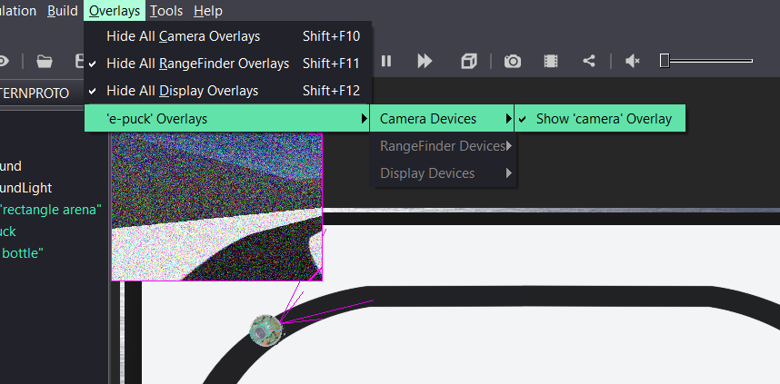
Figure 4. Webots camera overlays menu and robot’s camera image.
Solution
No solution is provided for this lab. A bare-bones template for the code is provided in the ZIP file, which can be used as a starting point for the implementation of your solution. Also check the solutions of previous labs and the Jupyter Notebooks for Mobile Robot Control.
Conclusion
After completing this lab you are able to combine many behaviors for a mobile robot to execute a complex mission.
Next Lab
In the next lab you will learn how to control a simulated robot with code running on a microcontroller board.
Go to Lab 8 - Hardware-in-the-Loop Simulation
Back to main page.